




How do injection molding quality standards address dimensional tolerances?




Injection molding quality standards address dimensional tolerances by providing rules for specifying, measuring, and controlling part geometry. They do not make every molded component automatically interchangeable or safe. The applicable drawing, material, measurement conditions, and agreed acceptance criteria determine what a compliant part must look like.
For a quality team, the practical question is not simply whether a dimension is inside a tolerance band. It is whether that band reflects the part’s function, can be measured consistently, and can be maintained across production without hiding risks from shrinkage, warpage, or process changes.
What standards do, and what the drawing must define
Dimensional requirements usually come from several connected documents. A product drawing defines nominal dimensions, tolerances, datums, and geometric requirements. A referenced technical standard may supply rules for interpreting those requirements or selecting general tolerances. The control plan then translates them into inspection characteristics, methods, frequencies, and reactions to nonconforming results.
Some standards address tolerances for molded plastic parts; others address geometric dimensioning and tolerancing, measurement, or quality management. A quality management certification can indicate that a manufacturer operates a documented management system, but it does not establish that a particular dimension meets its drawing requirement.
When a drawing invokes a standard, the referenced edition, scope, and any project-specific exceptions matter. A general tolerance should not override a tighter feature-specific requirement. Equally, a supplier should not assume that a tolerance table alone defines inspection conditions, part conditioning, or acceptance of a safety-critical feature.
Choose tolerances around function, not appearance
A molded housing may have an external length that affects appearance and a smaller snap-fit feature that controls assembly. Applying the same tolerance to both can add cost without improving the fit, while leaving the functional feature inadequately controlled.
Start with the mating condition and the consequences of variation. For each important feature, determine what happens at the allowable extremes: Will the part assemble? Will a seal remain compressed? Could a latch disengage? Consider the combined variation of mating parts, not just the molded component in isolation.
Linear dimensions alone may not describe the requirement. A hole can have an acceptable diameter but be incorrectly located; a sealing surface can have the correct overall size but be warped. Depending on the function, the drawing may need requirements for position, flatness, profile, or another geometric characteristic, together with meaningful datum references.
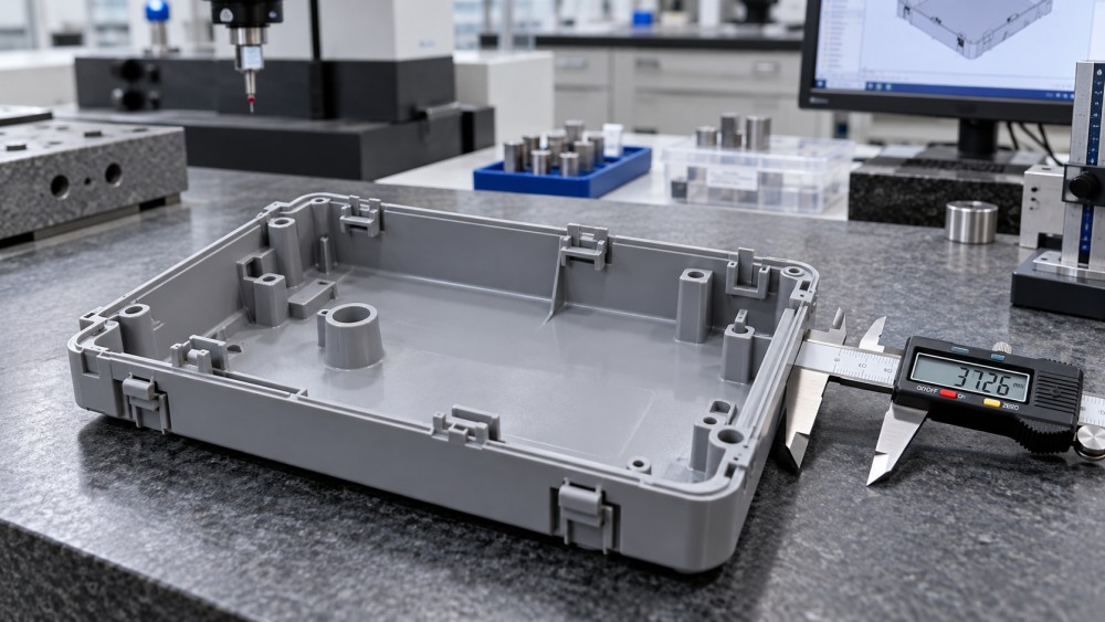
For features related to safety, the dimensional specification should connect to the relevant risk assessment and functional verification. A compliant measurement is evidence about the measured characteristic; it is not a substitute for an assembly, sealing, retention, or other performance test where that test is needed.
Why achievable precision depends on the molding process
Plastic does not leave the mold as a dimensionally fixed copy of the cavity. It cools and shrinks, and different regions can shrink by different amounts. Wall thickness, gate location, flow direction, cooling, part geometry, and processing conditions all influence the final shape.
Material selection also changes the tolerance discussion. Different polymers and grades behave differently during cooling and in service. Reinforcements can make dimensional behavior direction-dependent, while some materials absorb moisture and change dimensions after molding. A tolerance demonstrated on one resin or tool should not automatically be transferred to another.
Tool construction matters as well. Features formed across the parting line, by movable cores, or by separate inserts can introduce alignment variation. Multiple cavities may produce slightly different results, so an average across cavities can conceal a cavity that is consistently near or beyond a limit.
Before committing to a tight tolerance, review the proposed material, part design, mold concept, and measurement approach with the molder. Tightening a requirement may require tooling adjustments, more controlled processing, additional inspection, or a design change. Where a feature is difficult to mold reliably, a functional redesign or a justified secondary operation may be more practical than repeated tool corrections.
Measurement conditions are part of the result
Two teams can measure the same part and report different values if they use different datums, fixtures, instruments, or contact forces. Flexible plastic parts are especially vulnerable to distortion when clamped. A fixture that forces a warped part into shape may produce a repeatable number that does not represent the condition being accepted.
The inspection method should define the part orientation, datum establishment, measurement locations, and whether the part is measured free-state or restrained. Restraint can be appropriate when it represents the assembled condition, but it must be specified rather than introduced by the inspector. The method should also address conditioning and the time between molding and measurement when temperature, moisture, or continuing dimensional change could affect the result.
Choose equipment that suits both the feature and the required discrimination. Calipers can be useful for accessible dimensions, while optical systems, coordinate measuring machines, gauges, or functional fixtures may be better suited to other geometries. The measuring system itself should be evaluated for variation, including differences between operators where relevant. A measurement uncertainty or variation that is large relative to the tolerance makes acceptance decisions less reliable.
From first approval to production control
An initial dimensional report can show whether sampled parts meet requirements at a particular point in time. It does not, by itself, demonstrate that production will remain stable. The inspection plan should identify the characteristics to monitor, the sampling approach, and the response when results drift or fall outside limits.
For a multi-cavity mold, retain cavity identification where it is needed to investigate variation. Record the material and relevant production conditions alongside inspection results so that a dimensional shift can be traced to a meaningful change. Depending on the risk and production agreement, records may include tool identification, material lot, inspection method, measurement results, and disposition decisions.
A process change deserves particular attention when it can affect shrinkage or geometry. Changes to resin grade, tooling, a mold repair, processing settings, or measurement fixtures may require a documented assessment and renewed dimensional or functional verification. The scope should reflect the feature affected and the consequences of failure, rather than treating every change as equally significant.
When a result is out of specification, contain the potentially affected product, investigate the cause, and document its disposition under the agreed process. Do not treat sorting as proof that the process has been corrected. A concession or deviation, where permitted, should be approved by the authorized party and should not silently become the new tolerance.
What to settle before accepting a tolerance proposal
Review the drawing and inspection plan together before production approval. The most useful questions are:
- Does the tolerance protect the function? Check fit, location, form, and the combined variation of mating components.
- Is the requirement complete? Identify applicable standards, drawing revisions, material, datums, and any special conditioning or restraint.
- Can both parties measure it consistently? Agree on the method, fixture, measurement locations, and treatment of measurement variation.
- Can the process maintain it? Review representative results by cavity and assess stability for characteristics whose failure would have serious consequences.
- What happens when conditions change? Define notification, revalidation, containment, and disposition responsibilities.
GEMM’s technical and supplier resources can support the early comparison of materials, molding processes, and supply capabilities. The acceptance decision remains grounded in the part-specific drawing, agreed inspection method, production evidence, and required functional checks.
- Last One:No more articles
- Next Article:How does molecular weight affect polymer melt viscosity?Oct 31, 2026
Related News
- 00
0000-00
How do injection molding quality standards address dimensional tolerances? - 00
0000-00
How does molecular weight affect polymer melt viscosity? - 00
0000-00
How to track ore flows from the mine to the processing plant - 00
0000-00
Are sodium-ion batteries suitable for cold-climate energy storage? - 00
0000-00
How to use an application compatibility guide before an OS upgrade
Related tags
Weekly Insights
Stay ahead with our curated technology reports delivered every Monday.