




What Are the Common Weld Defects in Offshore Drilling Pipelines?




Offshore drilling pipeline welds fail for different reasons than comparable onshore welds. The weld may be made in a controlled fabrication yard, on a vessel with limited access, or during repair work in a harsh marine environment. It must then withstand internal pressure, cyclic loading, vibration, seawater exposure, cathodic protection conditions, and sometimes sour-service chemistry. A discontinuity that appears minor in a radiograph can become significant if it is located in a fatigue-sensitive weld toe, a high-stress girth weld, or a corrosion-prone area beneath coating.
The practical question is not simply whether a weld contains an imperfection. Nearly all welding processes create some level of geometric variation or metallurgical discontinuity. The critical issue is whether the discontinuity exceeds the acceptance limits in the governing project specification and whether it can reduce the pipeline’s intended pressure containment, fatigue life, fracture resistance, or corrosion performance.
Porosity and gas-related cavities
Porosity consists of gas pockets trapped in the solidifying weld metal. It can appear as isolated rounded indications, scattered pores, aligned pores, or clustered cavities. In offshore drilling pipelines, porosity is often associated with moisture, contaminated consumables, poor shielding gas coverage, surface contamination, or unstable welding conditions.
Hydrogen-bearing moisture is a particular concern. Damp electrodes, flux, or wire storage conditions can introduce moisture into the weld zone. Water, oil, salt deposits, paint, rust, and cutting residues on the pipe bevel can also generate gases during welding. For gas-shielded processes, wind, vessel movement, excessive torch distance, damaged gas hoses, or improper gas flow can disrupt shielding and allow atmospheric contamination.
Small isolated pores may be acceptable under some qualified welding procedures and project criteria. Clustered or linear porosity is more concerning because it can reduce effective weld cross-section and create local stress concentration. Where porosity occurs close to the fusion line or root, it may also indicate broader cleaning or shielding failures rather than a one-off event.
Radiographic testing is highly effective for identifying volumetric porosity. Ultrasonic testing may detect larger cavities but is generally more valuable for planar flaws. Prevention depends on disciplined consumable control, clean bevel preparation, stable shielding, dry storage, and verification that the selected welding parameters match the approved welding procedure specification (WPS).
Lack of fusion: a planar defect with high integrity consequences
Lack of fusion occurs when deposited weld metal does not properly bond to the parent pipe material or to a preceding weld bead. It may occur at the sidewall, between passes, or at the root. Unlike porosity, lack of fusion is a planar discontinuity. That geometry matters because crack-like planar features can propagate under cyclic loading more readily than rounded volumetric imperfections.
Common causes include insufficient heat input, incorrect electrode or torch angle, excessive travel speed, poor access around the joint, inadequate removal of slag between passes, and improper fit-up. In narrow-groove or thick-wall applications, the sidewall can be especially difficult to fuse consistently. A welder may produce an externally acceptable bead while leaving an unfused interface beneath the surface.
Offshore conditions can make this defect more likely. Restricted welding positions, changing pipe alignment, limited visibility, and motion-induced instability can alter arc control. Repair welding can add another layer of risk if the excavated area is not fully cleaned, shaped correctly, and examined before rewelding.
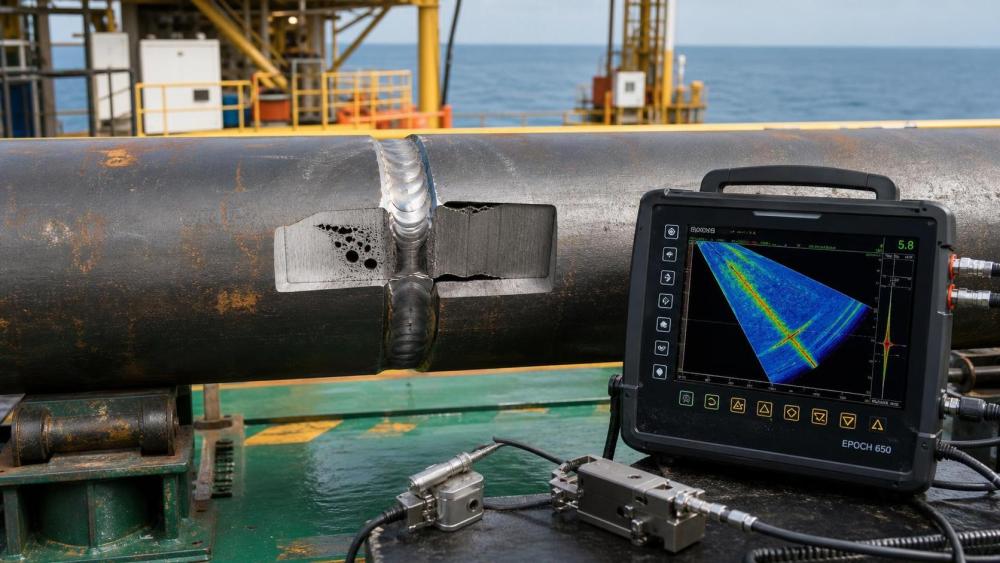
Conventional radiography may miss unfavorably oriented lack-of-fusion indications. Automated ultrasonic testing (AUT), phased-array ultrasonic testing (PAUT), and time-of-flight diffraction (TOFD), where applicable and qualified for the joint configuration, are better suited to detecting planar flaws. Detection capability still depends on procedure qualification, probe selection, scanning coverage, calibration blocks, operator competence, and the ability to distinguish relevant indications from weld geometry.
Incomplete penetration and root defects
Incomplete penetration means the weld metal has not fully extended through the intended joint thickness at the root. It is common in girth welds where root access, internal alignment, root opening, and welding process control are not maintained within the required range. A related issue is incomplete root fusion, where the root region appears filled but does not properly bond to one or both pipe edges.
These defects reduce the effective load-bearing section and can act as initiation points for fatigue cracking. In pressure-containing pipelines, a root defect is particularly important because it lies on or near the internal wetted surface. If the transported fluid is corrosive, contains chlorides, carbon dioxide, hydrogen sulfide, solids, or aggressive drilling-related chemicals, a root profile irregularity can become a site for localized corrosion or erosion.
Typical causes include an undersized root gap, excessive land thickness, poor hi-lo control, incorrect root pass parameters, insufficient current, high travel speed, and inadequate access for the chosen process. Internal line-up clamps and fit-up controls are therefore not merely productivity tools; they are part of weld integrity control.
Root defects are often assessed through radiography or qualified ultrasonic methods. Visual inspection remains useful before welding: it can identify misalignment, damaged bevels, incorrect root opening, and contamination before they become subsurface defects. Once the joint is filled, visual inspection alone cannot establish root soundness.
Cracks: the defect category that requires immediate attention
Cracks are generally treated more severely than rounded discontinuities because they have sharp tips and can grow under stress. They may be longitudinal, transverse, crater-related, toe cracks, root cracks, or located within the heat-affected zone (HAZ). Their mechanism must be understood before repair, because simply grinding and rewelding a visible crack may reproduce the same failure.
Hydrogen-assisted cold cracking can occur after weld cooling, often in hardenable steels or restrained joints. It requires a combination of diffusible hydrogen, susceptible microstructure, tensile stress, and sufficiently low temperature. Sources of hydrogen include moisture in consumables, wet surfaces, and inadequate preheat practices. Thick-wall pipe, high-strength materials, and highly restrained attachments increase the need for controlled heat input and hydrogen management.
Hot cracking occurs during weld solidification when the weld metal cannot accommodate shrinkage stresses. It can be linked to material chemistry, unsuitable filler metal selection, excessive restraint, joint design, or welding parameters that create an unfavorable bead shape.
Fatigue cracking may initiate after the pipeline enters service. Weld toe undercut, poor cap profile, misalignment, residual stress, and repeated loading can all raise local stress concentration. Offshore riser-connected systems, piping exposed to vibration, and lines affected by pressure cycling require particular attention to weld geometry even where a defect meets minimum volumetric acceptance limits.
Surface-breaking cracks can be found using magnetic particle testing (MT) on ferromagnetic materials or liquid penetrant testing (PT) on suitable clean, nonporous surfaces. UT methods can identify subsurface cracking, while radiography has limitations for tight planar cracks unless their orientation is favorable. Where hydrogen cracking is a credible risk, delayed inspection after an appropriate holding period may be specified by the governing procedure or project requirements.
Undercut, overlap, and unacceptable weld profile
Not every damaging weld condition is hidden below the surface. Undercut is a groove melted into the parent material adjacent to the weld toe and not adequately filled by weld metal. It is usually caused by excessive current, excessive arc length, poor electrode angle, unstable manipulation, or excessive travel speed. On a fatigue-loaded line, undercut at the weld toe can be more consequential than its apparent size suggests because it creates a notch-like stress raiser.
Overlap is the opposite profile problem: weld metal rolls onto the parent surface without proper fusion at the edge. It can trap crevices, obstruct coating application, and conceal lack of fusion. Excessive reinforcement, abrupt cap transitions, spatter, arc strikes, and poor blending of repaired areas can also affect fatigue performance and coating quality.
Visual testing (VT), supported by weld gauges and profile measurement where required, is the primary method for detecting these conditions. It should occur before non-destructive testing, not after it. A clean, accessible, properly illuminated weld surface is necessary for both visual acceptance and reliable MT or PT examination.
Slag inclusions and other non-metallic inclusions
Slag inclusions occur when flux residue or oxide material becomes trapped between weld passes or along sidewalls. They are associated with inadequate interpass cleaning, poor bead placement, low heat input, narrow joint geometry, and incorrect welding technique. In shielded metal arc welding and flux-cored processes, disciplined slag removal is essential before each subsequent pass.
Inclusions may be elongated and can resemble lack of fusion on some inspection records. Their significance depends on size, orientation, location, and applicable acceptance requirements. A repeated pattern of inclusions suggests that the problem is procedural: access, joint preparation, pass sequence, or cleaning practice may be incompatible with the actual production conditions.
Radiography can identify many slag inclusions because of their density contrast with weld metal, although interpretation must distinguish them from other volumetric indications. Qualified ultrasonic examination can also detect them, particularly when the inspection technique has been demonstrated for the relevant pipe thickness and weld configuration.
Burn-through, excessive penetration, and root concavity
Root quality is not improved simply by applying more heat. Excessive penetration can produce a protruding internal bead that impedes flow, complicates pigging, or creates turbulence and erosion sites. In thin-wall pipe, excessive heat can cause burn-through, leaving a hole or severely weakened root region. At the other extreme, root concavity reduces the weld throat and can compromise the required effective section.
These conditions are influenced by root opening, land thickness, welding current, arc force, travel speed, and backing or purge arrangements. The correct balance depends on the pipe wall thickness, process, welding position, and service design. A procedure qualified for one diameter, wall thickness range, or position should not be assumed suitable for a materially different offshore joint configuration without confirming its qualification limits.
Why offshore weld defects are often linked to process control failures
Defects are often described as welder performance issues, but that explanation is incomplete. A qualified welder can still produce unacceptable welds if fit-up varies, bevels are damaged, consumables are exposed to moisture, preheat is not maintained, or the production environment prevents stable shielding and access.
A useful control sequence begins before arc initiation. Pipe material certificates and heat numbers must remain traceable where required. Bevel geometry, root gap, alignment, cleanliness, and restraint should be checked against the WPS. Filler materials need correct identification, storage, and conditioning. Preheat and interpass temperatures require measurement rather than visual estimation when they are specified. Welding parameters should remain within the qualified range, including heat input controls where applicable.
Inspection should be matched to the defect mechanisms that matter. Visual examination is indispensable for fit-up and surface profile but cannot replace volumetric or planar-flaw inspection. Radiography provides a strong record for many volumetric imperfections. AUT, PAUT, and TOFD can offer better capability for certain planar defects, but only when the procedure is validated for the pipe, weld preparation, material, and acceptance criteria involved. No examination method is universally superior outside its qualified application.
Acceptance criteria cannot be transferred casually between projects
Pipeline weld acceptance is not determined by a single universal defect limit. Applicable requirements may derive from the owner’s specification, design code, welding code, classification requirements, material grade, service environment, and inspection method. Standards commonly encountered in pipeline and offshore work include API 1104, DNV-ST-F101, ISO welding qualification standards, and project-specific requirements, but their use and hierarchy depend on the contract and system design.
A defect that is acceptable under one radiographic criterion may not be acceptable under an engineering-critical assessment, a fatigue-sensitive design requirement, or a sour-service specification. The acceptance rule must also match the inspection technique. Comparing an ultrasonic indication directly with a radiographic limit without an approved equivalency basis can create false confidence.
Practical prevention priorities
The most effective prevention measures are usually basic, but they must be consistently enforced: protect consumables from moisture; clean the bevel and adjacent pipe surface; control fit-up and hi-lo; use a qualified WPS within its approved limits; maintain suitable preheat and interpass temperature; remove slag between passes; stabilize gas shielding; and inspect repairs as rigorously as original welds.
When repeated indications appear, the response should focus on pattern recognition rather than isolated repair. Recurrent sidewall lack of fusion points toward access, torch angle, heat input, or groove design. Root porosity points toward cleanliness, moisture, or shielding. Delayed cracking requires review of hydrogen control, restraint, material hardenability, and thermal practice. Repeated repairs without correcting the underlying mechanism can increase residual stress, alter local metallurgy, and consume allowable repair cycles.
In offshore drilling pipelines, weld quality is therefore best treated as a controlled system rather than a final inspection result. The strongest defense against leaks and integrity failures is the combination of qualified procedures, disciplined production control, inspection methods suited to the expected flaw types, and acceptance decisions tied to the actual service conditions of the line.
Related News
- 00
0000-00
Which sectors are driving demand in the chemical engineering market? - 00
0000-00
How to assess lifecycle emissions from CCUS for low-carbon cement - 00
0000-00
How do energy storage technologies compare for 8-hour discharge? - 00
0000-00
Do mill test reports prove industrial alloys meet ASTM standards? - 00
0000-00
How to verify plastic recycling system suppliers' throughput claims
Related tags
Weekly Insights
Stay ahead with our curated technology reports delivered every Monday.