




Ductile Iron Pipe Joint Failures: Causes, Inspection, and Prevention




A leaking pipe joint rarely starts as a simple “bad gasket” problem. In water distribution and utility networks, the visible symptom may be a damp chamber, pressure loss, soil washout, or a localized drop in flow. The underlying cause can sit much earlier in the chain: an unsuitable joint type, inadequate trench support, contamination during assembly, pipe deflection, damaged coating, or pressure conditions that exceed what the installed connection can tolerate.
For maintenance teams, joint failures matter because they can develop into broader operational problems. Escaping water may undermine bedding, migrate along the trench, damage adjacent assets, or create repeated callouts at the same location. A repair that addresses only the leak point without identifying the loading condition often produces a short-lived result. Effective after-sales maintenance begins with determining whether the joint failed because of assembly, movement, corrosion, hydraulic events, or an incompatibility between the installed components.
How ductile iron pipe joint failures usually appear
Joint problems do not always begin with a visible jet of water. In buried systems, early indicators can be subtle and may be mistaken for unrelated network issues. Maintenance personnel should compare site observations with recent operational and construction history before deciding on a repair method.
- Persistent damp soil or standing water: Water appearing near a valve chamber, road edge, or exposed fitting may indicate leakage at a bell-and-spigot connection or at a restrained assembly.
- Unexpected pressure decline: A pressure drop during stable demand conditions can point to leakage, although pump performance, valve position, and air management should also be checked.
- Discolored water after disturbance: Soil intrusion through a compromised joint, or internal deposits disturbed by pressure changes, can affect water appearance.
- Joint separation or abnormal gap: A changed insertion depth, exposed spigot, or displaced restraint component suggests movement rather than a purely sealing-related issue.
- Repeated leaks at bends, tees, and valve connections: These locations may be exposed to thrust, settlement, or concentrated loads that straight runs do not experience.
A leak at the joint should be differentiated from wall damage, fitting defects, service connection leakage, and leakage traveling through granular bedding from another source. Excavating directly over the wettest spot can be misleading when water has migrated along the trench. Isolation tests, pressure observations, and a review of the pipe alignment often provide a better starting point.
Why joints fail: the main mechanisms
Incorrect assembly and gasket damage
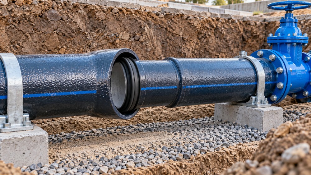
Push-on joints depend on correct seating of the elastomer gasket, a clean socket, appropriate lubrication, and controlled insertion. A gasket can roll, twist, become displaced from its groove, or trap sand and stones during installation. Excess lubricant does not correct a contaminated joint, while insufficient compatible lubricant can make insertion difficult and increase the risk of gasket displacement.
Problems may remain hidden until the line is pressurized. A joint can appear fully assembled from outside while the gasket has not seated evenly around the circumference. In other situations, the spigot is inserted beyond or short of the required witness mark, leaving insufficient engagement or creating an unfavorable geometry for movement.
Deflection, settlement, and inadequate support
Buried pipelines are affected by the soil system around them. Poorly compacted bedding, voids beneath the barrel, uneven trench bottom conditions, or backfill placed without sufficient side support can create localized bending. When a joint is asked to accommodate more angular deflection than intended, the gasket may lose uniform contact pressure. The result can be a slow leak that worsens after traffic loading, seasonal moisture changes, or nearby excavation.
Settlement is particularly important near transitions between native soil and imported backfill, at crossings, around structures, and near chambers. A repair crew should examine the pipe barrel and surrounding support, not merely replace the gasket. If the support condition remains unchanged, a newly assembled joint may be forced out of alignment again.
Thrust and longitudinal movement
Changes in direction, diameter, flow velocity, and pressure create forces that can move pipe segments. Bends, reducers, tees, dead ends, and valve assemblies need a design approach that addresses thrust through restraint, thrust blocking, or another engineered arrangement suitable for the site. If restraint is absent, incorrectly installed, or compromised by disturbed soil, joints can pull apart over time.
Pressure transients are another concern. Rapid valve operation, pump starts and stops, air release issues, and sudden changes in demand can create short-duration pressure events. Even when no visible separation occurs, repeated movement may reduce sealing reliability. Maintenance records showing leaks after operational events should prompt a review of surge control and valve operating practices.
Corrosion and coating-related damage
Ductile iron is commonly selected for buried water applications because of its strength and practical jointing options, but external conditions still require assessment. Aggressive soils, standing groundwater, stray-current exposure, damaged external protection, or unsuitable repair materials can affect long-term asset condition. Corrosion around a joint can also make future disassembly more difficult and obscure the original source of leakage.
Joint areas deserve close attention because protective coatings may be damaged during handling, field cutting, assembly, or excavation. A coating defect does not automatically mean the joint will leak, yet it can become part of a longer-term failure pathway when the surrounding environment is corrosive.
Inspection should establish the failure mode before repair
A disciplined inspection sequence helps avoid replacing serviceable parts or overlooking a network-level cause. The level of investigation should reflect the consequences of failure, access conditions, water quality requirements, and whether the location has a history of repeat events.
- Review the location and operating history. Identify the joint type, pipe diameter, nearby fittings, recent excavations, pressure changes, valve operations, and prior repairs. A leak near a bend requires a different line of inquiry from a leak in a long, straight run.
- Confirm that the joint is the source. Use isolation where practical, observe pressure behavior, and inspect adjacent connections. Water can travel along bedding material before surfacing.
- Expose enough of the assembly. A narrow excavation may hide barrel deflection, unsupported sections, damaged restraint hardware, or a misaligned fitting. Excavation should permit safe examination of the pipe, socket, surrounding soil, and joint engagement.
- Check alignment and insertion depth. Look for uneven joint gaps, exposed witness marks, axial pullout, angular deflection, and signs that the pipe has been bearing on a hard point.
- Inspect sealing and contact surfaces. Where disassembly is appropriate, examine the gasket for cuts, rolling, flattening, contamination, hardening, or incorrect placement. Check the socket and spigot for grit, scoring, coating damage, or deformation.
- Assess restraint and soil support. Inspect followers, bolts, gripping elements, anchoring arrangements, and the condition of bedding and backfill. Determine whether the pipe has moved because the surrounding support has changed.
- Document the evidence. Photographs, joint measurements, pipe markings, pressure observations, and soil conditions can help distinguish a one-off installation issue from a recurring construction or operational pattern.
For small-diameter sections such as DN100 water mains, crews sometimes underestimate the importance of alignment because individual pipe lengths are easier to handle than larger sizes. Yet DN100 installations can still be affected by service connections, valve pits, frequent directional changes, shallow cover, and local settlement. A buyer guide for water infrastructure should treat joint compatibility, gasket specification, fitting interfaces, and site handling requirements as part of the procurement decision rather than as field details to resolve after delivery.
Choosing the right repair approach
The repair method should match the confirmed failure mechanism. Reassembling a push-on joint may be appropriate when inspection finds a damaged or displaced gasket and the pipe alignment, socket, and spigot remain sound. The crew should clean contact surfaces thoroughly, use the specified gasket and compatible lubricant, align the barrel before insertion, and verify the insertion mark.
If the pipe has moved longitudinally, the repair scope may need to include restraint or restoration of the original thrust-control arrangement. Simply pushing the pipe back into the socket without addressing the source of movement can leave the connection vulnerable to another pressure event. Where settlement has created an unsupported span, re-establishing proper bedding and sidefill is often as important as the joint work itself.
Where corrosion, wall damage, or socket damage is present, the decision may shift from gasket replacement to cutting out and replacing a section, installing a suitable repair coupling, or rebuilding the connection with compatible components. The selected approach should account for pipe outside diameter, pressure duty, joint geometry, available access, and future maintenance needs. A temporary clamp can control an immediate leak but may not resolve pipe movement or deteriorated support conditions.
During planned rehabilitation or stock review, maintenance teams may need to compare joint systems, lining options, coatings, and available sizes for replacement work. Product information for ductile iron pipe systems can be useful when checking the basic relationship between pipe type, joint configuration, and water infrastructure requirements. The final specification should still be reconciled with the project drawings, applicable standards, pressure conditions, and the dimensions of existing fittings and valves.
Prevention begins before the line is buried
Many joint failures are preventable through better control of receiving, storage, installation, and acceptance testing. Pipes and fittings should be inspected on arrival for impact damage, distorted ends, coating damage, and missing or mismatched joint accessories. Gaskets should be stored away from conditions that can contaminate or degrade them, and crews should avoid mixing components when multiple joint designs are present on site.
Installation instructions should be available to the crew at the point of work, especially where restrained joints, mechanical assemblies, or nonstandard fittings are involved. A short pre-installation check can confirm the correct gasket orientation, cleaning method, lubricant, insertion depth, bolt tightening sequence where applicable, and allowable deflection. These details are easy to overlook under schedule pressure but directly affect sealing performance.
Backfilling deserves the same attention as joint assembly. Material placed around the lower sides of the pipe supports the barrel and limits later displacement. Large rocks, debris, or poorly compacted zones near the joint can introduce point loading or allow movement after the trench is closed. Compaction practices must suit the pipe system and local ground conditions; excessive force or poorly controlled equipment near exposed pipe can also create damage.
Maintenance records can reveal patterns that field repairs miss
A useful failure record captures more than a location and repair date. It should identify the joint type, pipe size, installation age where known, apparent failure mode, soil and groundwater conditions, nearby fittings, operating circumstances, repair materials used, and whether the bedding or restraint was restored. Over time, this information can reveal whether failures cluster around a particular construction practice, pressure zone, soil condition, or component interface.
For after-sales maintenance personnel, the practical objective is not to eliminate every leak with the fastest available repair. It is to restore service while reducing the chance that the same section fails again. That requires treating the joint as part of a connected system: pipe alignment, ground support, thrust control, pressure behavior, component compatibility, and installation quality all influence the result.
When inspection identifies the actual mechanism, repair decisions become more defensible. A clean, correctly seated gasket may solve an assembly-related leak; a displaced line may require support and restraint work; recurring failures near operational changes may call for a hydraulic review. The strongest preventive action is the one that removes the condition that allowed the joint to fail in the first place.
Related News
- 00
0000-00
Terephthalic Acid CAS 100-21-0: The Technical Checks Behind Stable Polyester Supply - 00
0000-00
What determines biofuel production capacity at commercial scale? - 00
0000-00
How to select industrial chemicals for pulp processing by furnish type - 00
0000-00
What Factors Affect Bioprocessing Yield in Small-Scale Plants? - 00
0000-00
Do Metal Physical Properties Change After Welding?
Related tags
Weekly Insights
Stay ahead with our curated technology reports delivered every Monday.